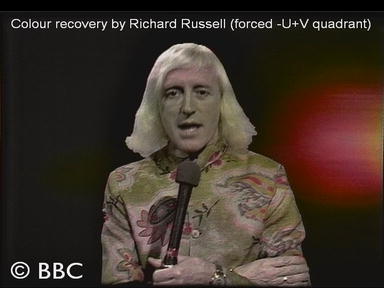
Richard Russell, 29th April 2008
Encouraged by Andrew Steer's results, I thought I would have a go at reproducing something myself. I only received the DVDs from James yesterday and all the code has been written this morning. My approach is, I think, basically the same as Andrew's but of course the detailed algorithm has been derived from scratch.
As the developer of the hardware Transform PAL Decoder I do have considerable experience of PAL to call upon (although my colour recovery experiments have nothing in common with that device!). For the moment I too have had to assume +V and -U, but like Andrew I have some ideas for expanding to the other three quadrants.
Given the extremely short time that I have been working on it I'm not too disappointed with the first results:
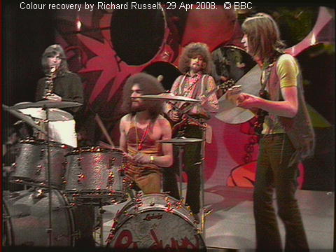
There has been no special tweaking to produce this image; the U and V gains are the same. I think it is slightly less saturated than Andrew's, but I've only set that by eye.
I can't promise to spend much more time on it (half a day total is quite enough!) but if I get a chance I'll experiment with some of my ideas for getting some blue into the picture.
Later 29th April
A couple of crude ideas tried, but no promising results. I don't think those other three quadrants are going to be easy!
For reference (and because Andrew has given some values) here are the parameters I used for the picture above:
Chroma bandpass filter: 31 taps FIR, 6dB bandwidth approx 3 MHz Diagonal UV-separation filter: 9 lines vertical aperture, 3 taps UV lowpass filter: 31 taps FIR, 6dB bandwidth approx 2 MHz
Note that because the frame is sub-Nyquist sampled vertically (1080 is less than twice 576), and therefore contains aliases, I decided against using more taps in the diagonal filter.
The FIRs are optimised using the Parks-McClellan algorithm, not simply windowed.
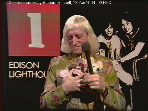
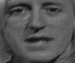
Here's the Jimmy Savile frame as processed using my algorithm; there may be a little more cross-colour than Andrew's version (or is it just in different places?):
30th April
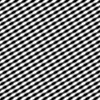
I tried increasing the number of taps to 47 (I prefer odd numbers because of the desirability of zero group-delay) but it didn't seem to make a significant difference. I initially thought it had, but I'd forgotten to compensate for the extra delay through the filter so what I was seeing was a misregistration of luminance and chrominance! This was the chroma bandpass filter I used:
Random thought: My algorithm is (as far as possible given the characteristics of the film recording) intra-field, that is the vertical filtering looks only at lines in the same field. This is a requirement if it is to work successfully with fast-moving material, when the two fields may be significantly different. Andrew Steer's Thoughts on the detail of the chroma and line-structure refers to "treating the combined image as if a single-field" so I wonder how that might be affected by motion.
21st May 2008
A brief diversion from my full gamut work to investigate an anomaly. Here are two consecutive frames (383 and 384) from the **JS lights** sequence, using the -U+V quadrant:
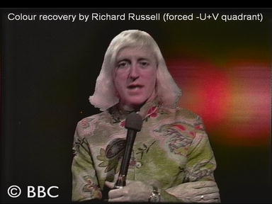
It's apparent that the hue of Jimmy's face is very different between these frames: too magenta in the first and too green in the second. But why? Looking closely at the subcarrier dot patterns, these are very different too:

I'm not too sure what's going on here, but it won't make colour recovery any easier!
26th May 2008
Triggered to some extent by Andrew Steer's work on an 'improved' chroma filter, I started to think about the spectrum of the chrominance in the film-recorded sequences. It's well known that U and V chrominance appear as diagonal patterns, U sloping down to the right and V sloping down to the left. A filter to separate them need only discriminate between these directions.
However once the two fields are combined to form a frame and upconverted to a higher vertical resolution, as in the 1080-line film recordings, the chrominance patterning is more complicated. Here for example is what the U colour subcarrier theoretically looks like:
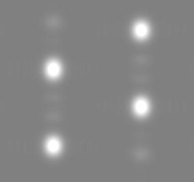
There is still a dominant pattern sloping down to the right, but there is another pattern sloping down (at a shallower angle) to the left. Here is the 2D spectrum of that same U subcarrier (1024x1024 FFT with Hanning window):

The blue lines are at horizontal frequencies of ±4.433 MHz and vertical frequencies of ±72 c/aph and ±216 c/aph. The two diagonal components (and their reflections about the origin) can be clearly seen as small white dots. The corresponding spectrum for V is as follows, showing the diagonals sloping in the opposite directions:
Here is the actual 2D spectrum of the chrominance in one of the more colourful film-recorded frames (frame 214 of the JS Lights sequence), showing the presence of both U and V components:

So, a 2D filter that will discriminate between the U and V chrominance in the film recordings, without throwing anything away, needs to be more complicated than a simple diagonal filter.
In the light of this investigation I have redesigned the chroma filter used in my Full Gamut Colour Recovery process. This is the result when fed with a zone plate:

The coloured blobs (forced +U+V quadrant) are centered on the ±4.433 MHz, ±72 c/aph and ±216 c/aph spectral components identified in the above FFTs.
The aliasing evident in the luminance is because the down-conversion filters (from 1920x1080 to 720x576) are designed to be 6dB down at (and approximately skew-symmetric about) the horizontal and vertical Nyquist limits of 6.75 MHz and 288 c/aph respectively. Experience gained in BBC Research & Development, where I specialised in designing scaling filters, indicates that this gives a good compromise between resolution and aliasing.
28th May 2008
For completeness, here are the U, V and Y zoneplate outputs separately. These allow the degree of crosstalk between the outputs to be judged more accurately:


Note that I didn't reduce the system gain from the value used for normal pictures, so the U and V outputs are quite heavily clipped, and the effective depth of the luminance subcarrier notches is probably affected by internal clipping.